
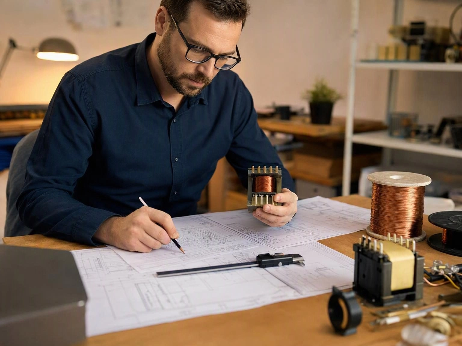
Specification Review Before Design
Custom magnetic component development begins with a review of the electrical and mechanical specification, not with a drawing. The reviewer needs to understand the circuit the component will serve, because the same electrical specification can be met by several different constructions with very different cost, size and thermal behaviour. A transformer specified only by turns ratio and inductance leaves the supplier guessing about leakage inductance, insulation and thermal margin.
- Input and output voltage and current, and the circuit topology
- Switching frequency and expected duty cycle range
- Target inductance, turns ratio and tolerance
- Maximum allowable leakage inductance and interwinding capacitance
- Insulation class, safety standard and creepage requirements
- Mechanical envelope, pin out, mounting method and maximum height
Design and Core Selection
With the specification understood, the engineer selects a core family and geometry, calculates turns and wire gauge, and evaluates the winding arrangement against the leakage and capacitance targets. This is where experience pays. A compact design that ignores fringing flux, or a winding scheme that produces an unexpectedly high interwinding capacitance, will fail at EMC testing long after the sample has been approved on the bench.
Prototyping and Measurement
The prototype is wound and measured against every parameter in the agreed specification, not only the headline inductance. Inductance and quality factor across frequency, leakage inductance, interwinding capacitance, DC resistance, insulation resistance and high potential strength are all recorded, and the component is measured at the temperature extremes the application will experience. Thermal behaviour is confirmed rather than assumed.
Typical Sampling Timelines
Timelines depend on how much of the design is new. Standard configurations wound to an existing core and bobbin are the fastest path. Completely new developments, unusual structures or components with specific safety approval requirements take longer because tooling, bobbins and insulation systems may need to be created and validated.
- Standard configuration samples generally within three to seven working days
- New development with tooling or special structure generally seven to fifteen working days
- Safety approval support adds time depending on the certification body
Sample Validation and Release to Production
Sample approval is a joint activity. The customer validates electrical and thermal performance in the real circuit, and confirms mechanical fit, assembly process compatibility and any safety requirements. Once approved, the specification is frozen, the production process is defined and the component moves to volume manufacture with the agreed test plan applied to every unit.
We handle this sequence for custom transformers, inductors and filters, working from a customer drawing or from stated electrical parameters and a mechanical envelope.