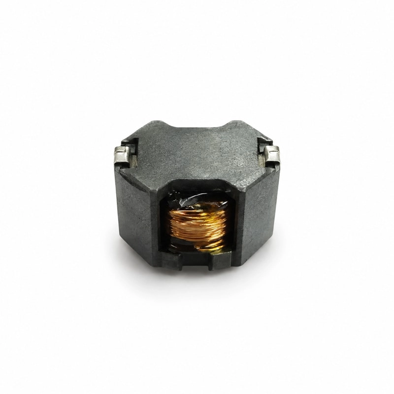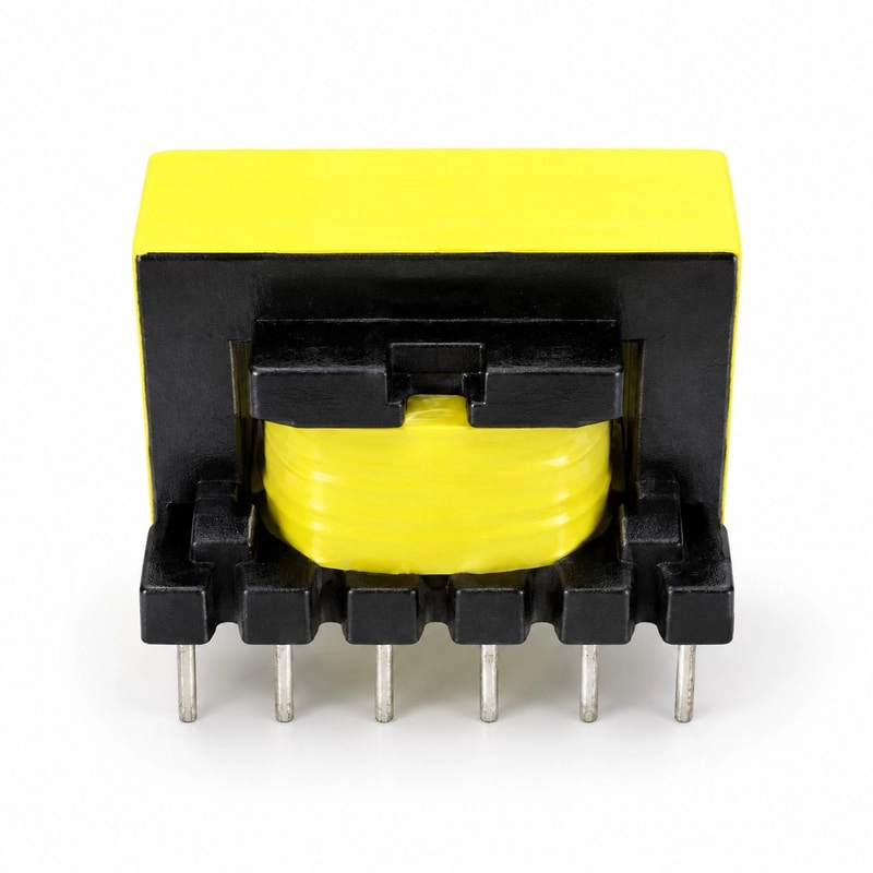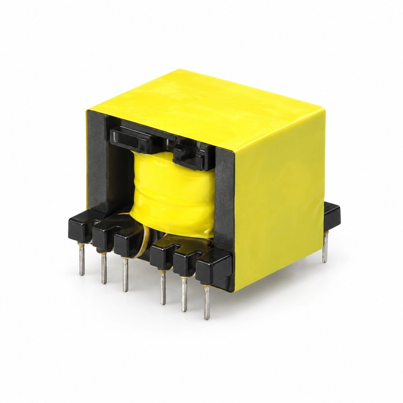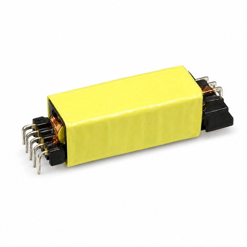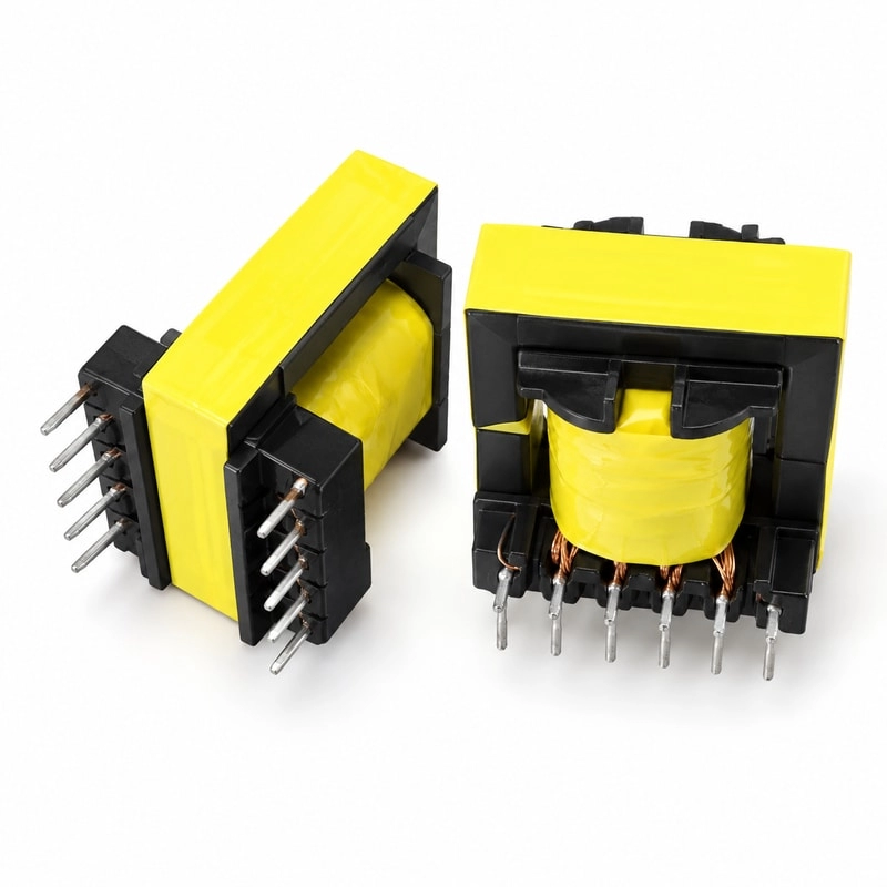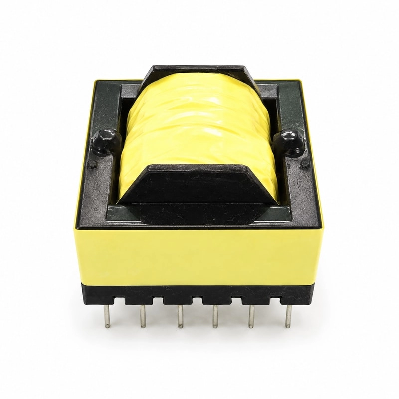

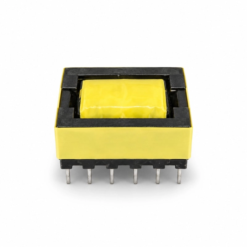
A flyback transformer is not simply an isolation transformer operated at high frequency. During the switch on-time it behaves as a coupled inductor and stores energy in its magnetic field. When the switch turns off, that energy is transferred to the secondary. This operating sequence makes the air gap, magnetizing inductance, turns ratio, leakage inductance and clamp network tightly connected. A change intended to improve one parameter can easily worsen another.
Start With the Converter Operating Envelope
Before choosing a core or calculating turns, define the full electrical envelope: minimum and maximum input voltage, output voltage and current, switching frequency, controller mode, maximum duty cycle, target efficiency, isolation requirement and maximum ambient temperature. The worst case is rarely a single operating point. Minimum input voltage tends to produce the highest primary current, while maximum input voltage can produce the highest MOSFET drain stress.
For discontinuous conduction mode, the transformer fully releases its stored energy during each cycle. In continuous conduction mode, some magnetizing current remains when the next cycle begins. Quasi-resonant and valley-switching controllers add another constraint because the reflected voltage and transformer capacitance influence the drain ringing pattern used for turn-on timing.
Turns Ratio Sets More Than the Output Voltage
The primary-to-secondary turns ratio determines the secondary voltage reflected back to the primary during the off-time. A higher reflected voltage can reduce secondary current and shorten the demagnetization interval, but it also raises the MOSFET drain voltage. A lower reflected voltage reduces MOSFET stress but increases secondary RMS current and may require a higher-current rectifier and heavier winding.
The practical design target is a reflected voltage that leaves enough margin between the sum of the input voltage, reflected voltage and leakage spike and the MOSFET rating. That margin must cover line transients, component tolerances and temperature. Designing only to the nominal input and nominal output is a common reason a prototype works on the bench and fails during surge or high-line testing.
Primary Turns and Flux Density
The minimum primary turns are set by the applied volt-seconds, the usable core area and the allowed flux-density swing. Too few turns drive the core toward saturation at high line or maximum duty cycle. Too many turns reduce flux density but increase copper resistance, winding capacitance and leakage because more layers are required.
Ferrite core loss rises quickly with both frequency and flux swing. The allowable peak flux density at room temperature is not automatically an acceptable design target at the maximum operating temperature. A reliable design leaves thermal and saturation margin rather than treating the material limit as a normal operating point.
Why the Air Gap Is Essential
Most of the energy in a flyback transformer is stored in the air gap, not in the ferrite. The gap lowers effective permeability, establishes the target magnetizing inductance and allows the core to carry substantial DC magnetizing current without saturating. Gap length therefore controls the relationship between inductance, peak current and stored energy.
- A gap that is too small produces high inductance but poor saturation margin.
- A gap that is too large requires more turns for the same inductance and increases fringing flux.
- Fringing near the gap can create local eddy-current heating in nearby copper.
- A distributed or carefully positioned gap can reduce concentrated fringing loss in higher-power designs.
Magnetizing inductance must be specified with a tolerance and a measurement condition. The nominal value alone does not describe peak current tolerance, because gap variation, core permeability and turns count all contribute to the result.
Leakage Inductance Creates the Drain Spike
Leakage inductance represents flux that links one winding but not the other. When the MOSFET turns off, current in this leakage path cannot transfer cleanly to the secondary, so it charges the MOSFET capacitance and produces a drain-voltage spike. The clamp or snubber must absorb that energy on every switching cycle.
Lower leakage inductance reduces clamp loss and switch stress. It is usually improved by placing primary and secondary windings closer together or interleaving them. However, tighter coupling also increases interwinding capacitance, which can worsen common-mode EMI and conducted noise. The winding structure must therefore balance leakage, capacitance and safety spacing rather than optimizing only one number.
Choosing a Clamp or Snubber
An RCD clamp is inexpensive and robust, but it dissipates the leakage energy as heat. A TVS clamp provides predictable voltage limiting but can also run hot at higher power. Active-clamp and energy-recovery approaches can improve efficiency, although they require more components and control complexity.
The clamp should be selected from measured leakage energy and worst-case peak current, not from a nominal leakage-inductance value alone. The physical transformer sample, MOSFET capacitance, layout inductance and diode recovery all affect the waveform. Final component values should be confirmed on the assembled converter across line, load and temperature.
Winding Arrangement and Insulation
Winding order changes electrical performance. A split primary around the secondary can reduce leakage, while a shield winding can reduce common-mode noise. Each added layer, margin tape and insulation barrier consumes window area and increases mean turn length. Reinforced insulation, creepage and clearance requirements must be included before the bobbin is selected.
Triple-insulated wire can simplify isolation in compact transformers, but it has a larger effective diameter and can reduce copper fill. Margin tape is straightforward but sacrifices winding width. The correct method depends on the safety standard, working voltage, pollution degree and mechanical envelope of the end product.
Copper Loss, Skin Effect and Temperature Rise
Primary and secondary currents are pulsed, so RMS current is substantially higher than average current. At high switching frequency, skin and proximity effects raise AC resistance beyond the DC resistance measured with an ohmmeter. Parallel strands, foil or litz wire may reduce loss, but they also change capacitance, termination complexity and manufacturability.
Temperature rise should be measured in the actual enclosure at the worst electrical condition. The hottest point may be inside the winding rather than on the core surface. A transformer that meets efficiency at room temperature can still have inadequate insulation life if the winding hotspot is not checked.
Information to Provide for a Custom Flyback Transformer
- Input voltage range and surge requirements
- Output voltages, currents and regulation priorities
- Controller, switching-frequency range and operating mode
- Target magnetizing inductance and allowable tolerance
- Maximum primary peak current and duty cycle
- MOSFET and rectifier voltage ratings
- Isolation standard, creepage, clearance and hipot requirement
- Maximum dimensions, ambient temperature and allowed temperature rise
- Leakage-inductance target and preferred clamp strategy
For compact offline designs, an EFD30 high frequency transformer offers a useful low-profile winding platform. The final core, gap and winding arrangement should still be calculated from the complete converter requirements rather than selected by power rating alone.
Prototype Validation Checklist
Measure magnetizing inductance, leakage inductance, turns ratio, DC resistance and hipot on the transformer before installing it. On the converter, verify peak drain voltage, primary peak current, secondary rectifier stress, clamp temperature, transformer hotspot, efficiency and conducted EMI at minimum input, maximum input and the load points that produce the highest stress. Recheck after thermal stabilization because copper resistance and core behavior change with temperature.
A well-designed flyback transformer is the result of coordinated electrical, magnetic, thermal, safety and manufacturing decisions. Treating the turns ratio, gap and winding structure as a single design problem produces a transformer that is easier to clamp, quieter in EMI testing and more consistent in production.