Why LED Drivers Are Demanding
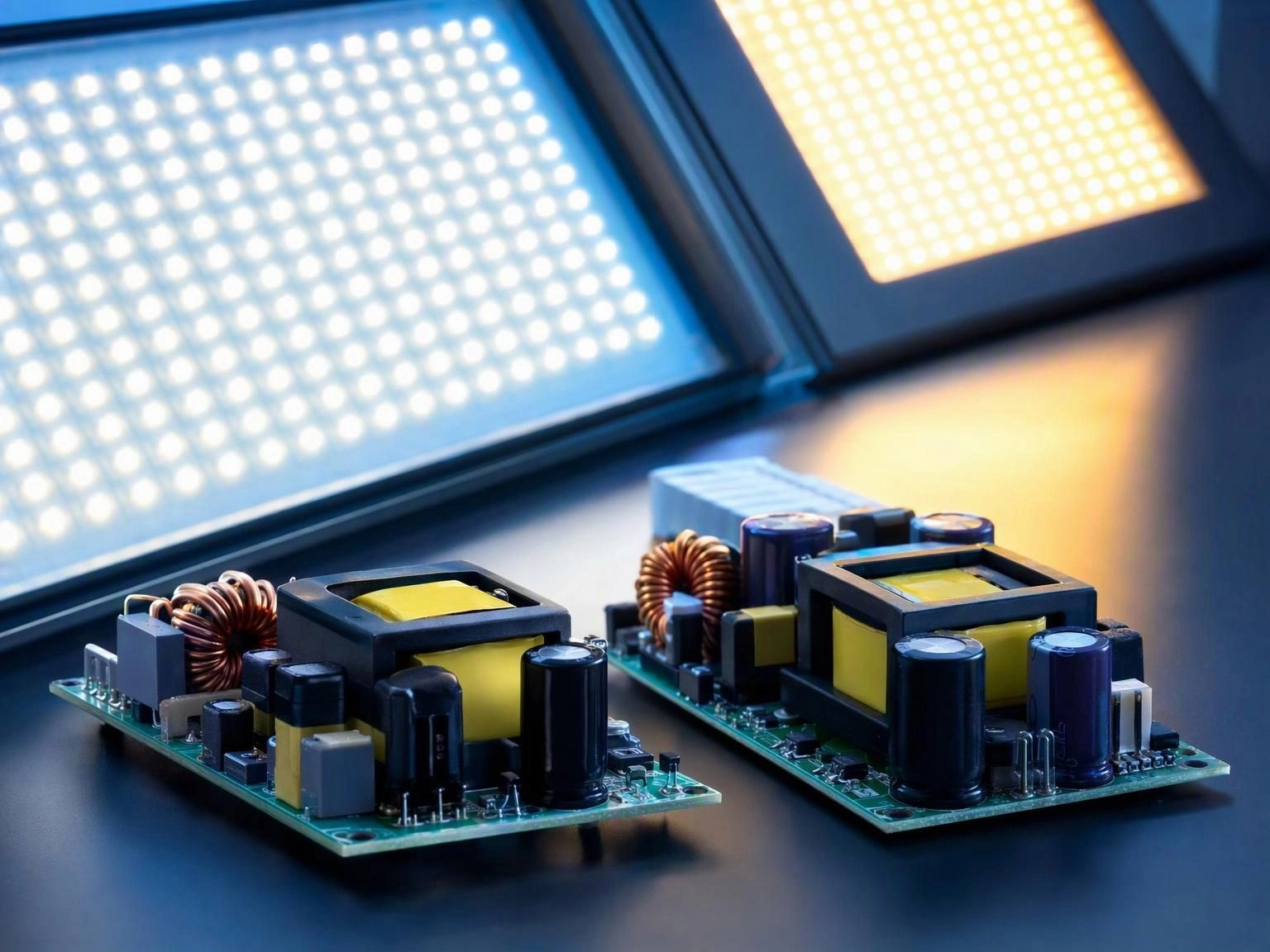
A LED driver is a constant current power supply that must hold its output within a tight tolerance over a wide input voltage range, at high efficiency, inside an enclosure that may have no active cooling, and often with a service life expectation measured in tens of thousands of hours. Every watt of loss inside the driver raises the junction temperature of the LEDs it feeds, which shortens their life. Loss in the magnetics is therefore not merely a bill of materials concern.
Isolated and Non Isolated Topologies
Non isolated buck drivers are simple and efficient where the LED string can share a ground with the mains derived supply, which is why they dominate retrofit lamps and low cost luminaires. Isolated flyback drivers separate the output from the mains, which is required for safety in many outdoor, industrial and accessible installations, and they need a transformer rather than a simple inductor.
The transformer in an isolated driver must meet the creepage and clearance requirements for the insulation class, which in an offline application usually means reinforced insulation and a construction that keeps primary and secondary physically separated with adequate margin through the bobbin and any tape barrier.
Core Selection for Lighting Applications
Low profile is frequently the deciding factor. EFD and EP cores offer a small height for slim driver enclosures, while PQ and EE cores provide better thermal mass and winding room where the enclosure permits. For the output filter inductor, drum core and moulded shielded types are common, with the shielded choice preferred when the driver sits close to sensitive dimming control circuitry.
- EFD and EP cores where height is the binding constraint
- PQ and EE cores for higher power drivers with more space
- Drum core inductors for output filtering at moderate current
- Moulded shielded inductors when EMI or adjacent circuitry is a concern
- Common mode chokes where conducted emissions limits are tight
Efficiency and Thermal Design
Core loss and copper loss both convert directly into heat inside a sealed enclosure, and the temperature rise they cause is what ultimately limits output power. Using a lower loss core material at higher switching frequency can reduce the size of the transformer, but only if the copper loss does not rise faster than the core loss falls. The winding is usually the hottest point in the component, so wire selection and thermal path deserve as much attention as core choice.
Life and Reliability
Long service life expectations make insulation quality critical. Varnish impregnation fixes the winding, prevents movement under thermal cycling and improves dielectric strength, and its absence is a common cause of premature failure in drivers that are otherwise well designed. Thermal cycling is the real test, not a single measurement at room temperature.
We supply high frequency transformers and inductors for LED driver applications in low profile core families with insulation and creepage construction matched to the safety standard the luminaire must meet.