A power inductor is often selected from a table using only nominal inductance and rated current. That shortcut can work for a low-stress prototype, but it does not define how the component will behave at peak current, switching frequency or operating temperature. For a custom inductor, the specification should describe the converter waveform and the required behavior under that waveform.
Begin With the Current Waveform
In a buck converter, the inductor normally carries the output DC current plus a triangular ripple. In a boost converter, it carries the input current plus ripple, and current can rise sharply at low input voltage. The important current values are average current, RMS current and peak current. They govern different limits.
- Average current is useful for understanding the operating point.
- RMS current determines most of the copper heating.
- Peak current determines saturation margin.
- Ripple amplitude drives core loss and output-current ripple.
Supply the minimum and maximum input voltage, output voltage, output current, switching-frequency range and converter topology. From those values, the inductor ripple and worst-case peak current can be calculated for each operating corner.
Set the Inductance From the Allowed Ripple
Higher inductance reduces ripple current but normally requires more turns, a larger core or a smaller effective gap. Those changes can raise DC resistance, size and cost. Lower inductance improves transient response and may reduce copper length, but it increases peak current, output ripple and switching-device stress.
The useful target is therefore not the largest inductance that fits. It is the inductance that holds ripple within the converter's control and output-capacitor limits while leaving acceptable transient response and saturation margin.
Inductance should be stated at a defined test frequency and signal level, together with its tolerance. For a power design, it should also be defined at the relevant DC bias or accompanied by an inductance-versus-current curve.
Distinguish Saturation Current From Thermal Current
Saturation current and rated current describe different failure mechanisms. Saturation current is the current at which inductance falls by a specified percentage, often 10, 20 or 30 percent. Thermal current is the current that produces a specified temperature rise, often 40 degrees Celsius, under stated test conditions.
A component can pass the thermal-current requirement and still saturate during a transient. It can also maintain inductance at peak current but overheat because its winding resistance is too high. Both limits must be above the corresponding current in the converter, with margin for tolerance and temperature.
Define Acceptable Inductance Roll-Off
Different core materials lose inductance in different ways. Gapped ferrite can maintain inductance well and then approach saturation more abruptly. Powder cores such as sendust or iron powder usually show a softer roll-off over current. A soft-saturation core may tolerate brief overloads gracefully, while ferrite can offer lower core loss at high frequency when properly gapped.
The converter does not necessarily require the full zero-bias inductance at peak current. What matters is that the minimum inductance at peak current remains high enough to keep ripple and control-loop behavior within limits. Put that requirement in the specification directly.
Calculate Copper Loss With RMS Current
DC copper loss is approximately the square of RMS current multiplied by winding resistance. Because resistance increases with temperature, a room-temperature DCR value understates the loss after the inductor heats. The specification should state DCR at a defined temperature and use hot resistance when estimating the final thermal result.
At higher switching frequencies, AC winding loss adds to the DC loss. Skin effect and proximity effect concentrate current within the conductor, especially in tightly packed multi-layer windings. Multiple strands can help, but only when the strand diameter and arrangement suit the frequency range.
Include Core Loss From Ripple Flux
Core loss depends on core material, switching frequency, flux-density swing and temperature. It cannot be predicted from DC current alone. Two inductors with the same inductance, DCR and size can have different core loss because their materials and gaps are different.
For high-frequency converters, provide the actual switching-frequency range and ripple current. If the controller changes frequency with load, include the significant operating points. The highest loss may occur at an intermediate load where frequency and flux swing combine unfavorably rather than at full load.
Shielding and Magnetic Field Requirements
An open drum core is economical and offers good winding access, but it produces more external magnetic field than a shielded construction. That field can couple into current-sense traces, audio circuitry, antennas or nearby metal. A shielded drum, molded inductor or closed magnetic path is preferable when the layout is sensitive or EMC limits are tight.
Shielding is not free. It can increase cost, alter saturation behavior and reduce heat dissipation. State whether the inductor is close to sensitive circuitry and whether a maximum stray-field requirement applies.
Mechanical and Environmental Inputs
Define the maximum footprint and height, mounting style, lead arrangement, vibration level, ambient-temperature range, cooling conditions and any coating or impregnation requirement. A temperature-rise result measured in still air on an open bench may not represent an inductor installed beside hot semiconductors inside a sealed enclosure.
For through-hole designs, lead diameter and spacing affect both mechanical retention and current capacity. For applications with vibration or audible-noise concerns, varnish impregnation can stabilize the winding and reduce movement.
Recommended Power Inductor Specification
- Topology: buck, boost, buck-boost or another converter type
- Input and output voltage ranges
- Switching-frequency range and control mode
- Nominal inductance and tolerance at a stated test condition
- Minimum inductance at the specified peak current
- Average, RMS and peak current
- Maximum DCR at a stated temperature
- Maximum allowed temperature rise and ambient temperature
- Core material preference or required saturation characteristic
- Shielding, size, mounting, vibration and environmental requirements
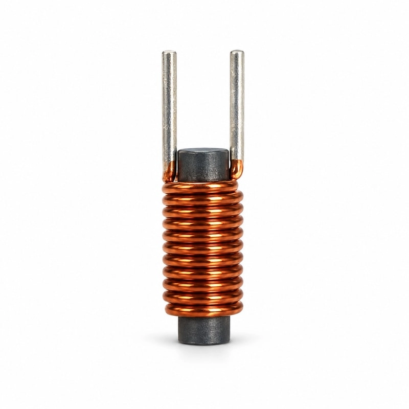
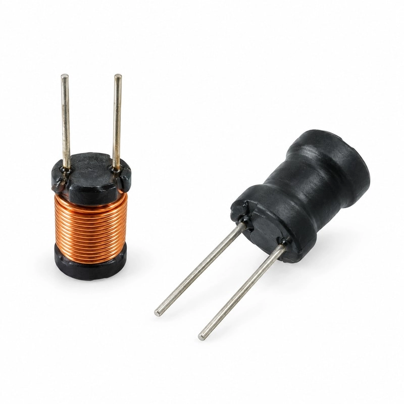
For cost-sensitive through-hole converters, a DR8 x 10 drum core inductor can be customized by changing turns, wire gauge and core characteristics. A rod core inductor may suit applications that prioritize simple construction and a specific field distribution. The correct format depends on the current waveform, EMI environment and mechanical constraints.
Validate the Inductor in the Converter
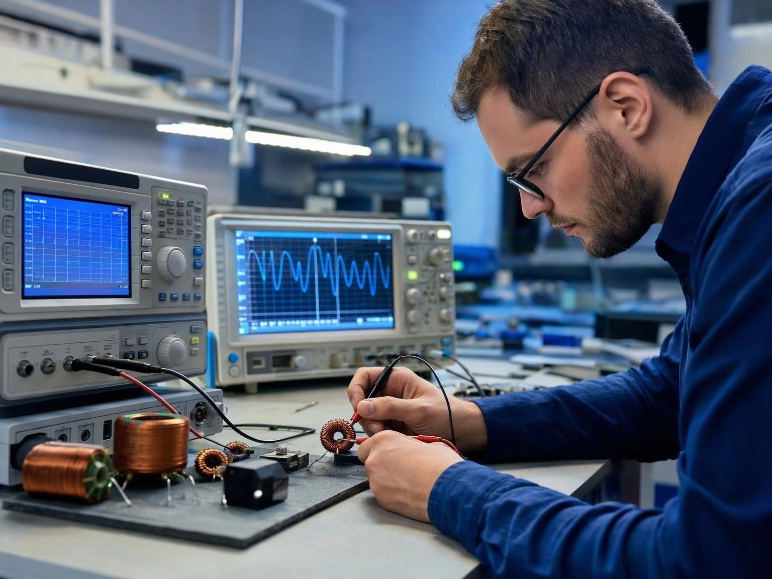
Bench validation should measure ripple current, peak current, switch-node behavior, efficiency and inductor temperature across input voltage and load. Check the transient condition that produces the highest current, not only steady full load. After thermal stabilization, confirm that inductance has not fallen enough to create a runaway increase in ripple.
It is also useful to compare measured winding temperature with calculated copper loss. A large mismatch may indicate significant core loss or AC winding loss. This feedback helps refine wire choice, gap, core material and winding geometry before production.
A Good Specification Makes Production Repeatable
The best custom-inductor specification defines performance at the conditions the converter will actually impose. Nominal inductance and a catalogue current rating are only the starting point. When bias behavior, DCR, ripple, frequency, temperature rise and mechanical limits are stated explicitly, the supplier can design toward measurable acceptance criteria and production lots can be compared consistently.