
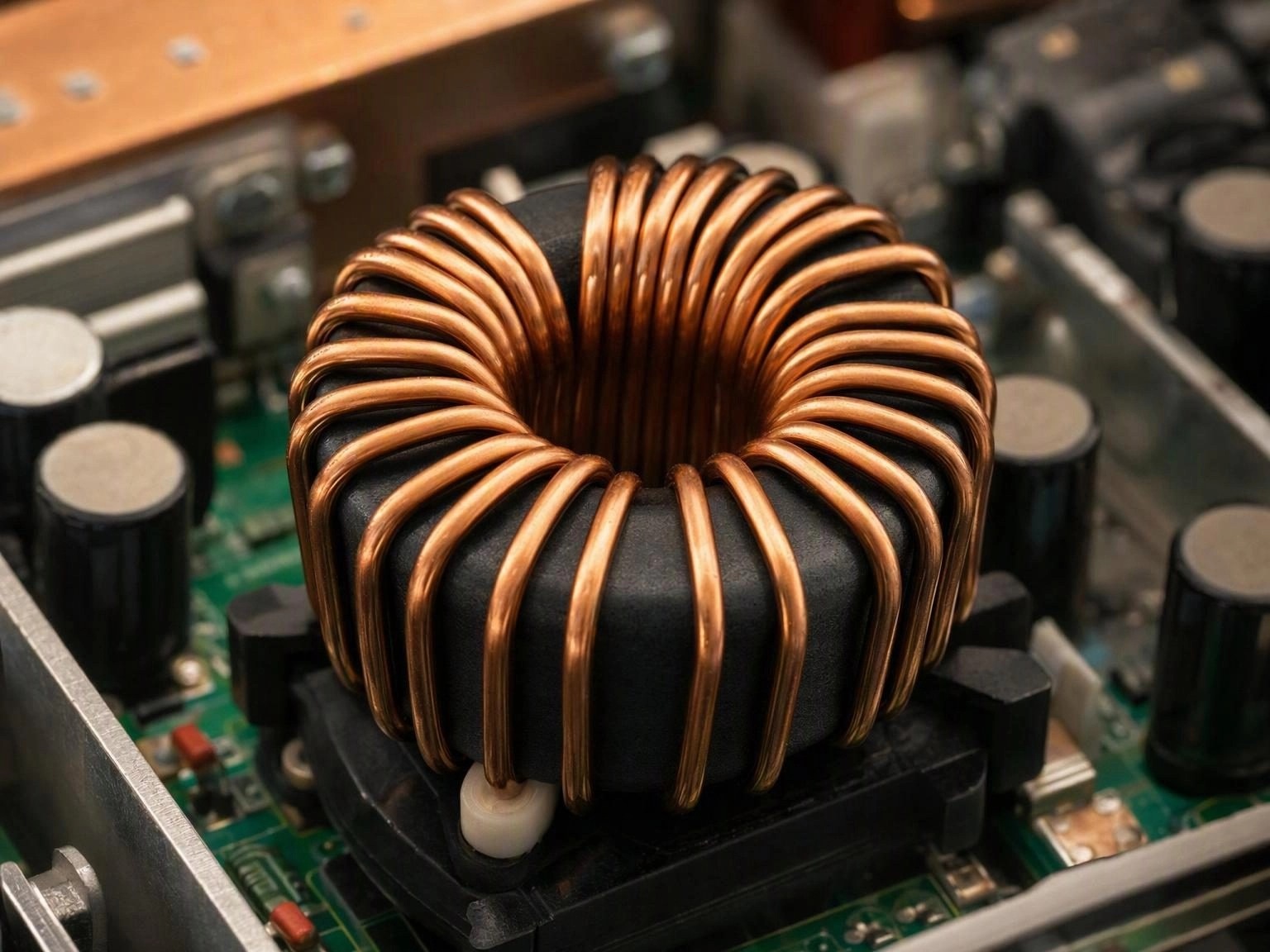
Why Power Factor Correction Exists
A simple bridge rectifier followed by a bulk capacitor draws current in narrow pulses near the peak of the input sine wave. The result is a poor power factor and a rich harmonic spectrum that wastes distribution capacity and disturbs other equipment on the same supply. Regulations in most markets now require active power factor correction above roughly 75 watts, and the boost converter is the circuit of choice for the task.
The PFC Inductor Carries a DC Bias Plus a Ripple
Unlike a filter inductor, the PFC inductor in a continuous conduction boost stage carries a large DC component at the line frequency with a high frequency triangular ripple superimposed on it. At the peak of the input sine wave the instantaneous current can be several times the RMS value. The core must remain out of saturation at that peak while still delivering enough inductance to keep the ripple current and the resulting harmonic distortion within limits.
This combination of high DC bias and high frequency ripple is what makes the PFC inductor one of the more demanding magnetics in a power supply.
Core Material Trade Offs
Gapped ferrite offers high permeability and low core loss but saturates abruptly, so the gap must be sized generously and the winding must accommodate the fringing field around a large air gap. Iron powder and sendust cores saturate softly, which allows a more compact design at the cost of higher core loss and lower permeability. Nanocrystalline and amorphous options appear in higher power designs where loss density dominates the decision.
- Gapped ferrite for low core loss where saturation can be controlled by an adequate gap
- Sendust and iron powder for soft saturation and compact high current designs
- Nanocrystalline and amorphous for high power stages with tight loss budgets
- Toroidal and block formats depending on winding cost and thermal path
Losses and Temperature Rise
Total loss in a PFC inductor has two parts. Core loss scales with flux swing, frequency and core volume, and iron powder cores give up core loss to gain saturation margin. Copper loss follows the RMS current and rises further because the high frequency ripple concentrates current near the conductor surface. In a well designed inductor the copper loss usually dominates, and the winding is the hottest part of the component.
Thermal design therefore focuses on the winding, meaning wire gauge, number of strands, bobbin fill factor and the path from winding to ambient or to a heatsink.
Specifying a PFC Inductor
Provide the input voltage range, output power, switching frequency, target inductance with tolerance, peak current at minimum input voltage and maximum line, RMS current, allowable temperature rise, insulation class and mechanical envelope. Harmonic distortion targets should also be stated, since they translate directly into an inductance requirement at the line peak.
Our team regularly reviews PFC specifications alongside the customer converter design to confirm that the inductance and saturation margin leave room for the harmonic limits the end product must meet.