Start With Switching Frequency and Power Level
The first two numbers that define a high frequency transformer are the switching frequency of the converter and the power the stage must deliver. A flyback running at 65 kHz and a forward converter running at 200 kHz place very different demands on core loss, winding AC resistance and insulation. Once those two values are fixed, the core families that can physically satisfy the design narrow quickly, and the rest of the selection becomes a set of trade offs rather than guesswork.
We ask for these two figures before anything else, because they determine whether the design belongs in a compact EP or EFD bobbin or needs the thermal mass of a PQ or ETD core.
Core Geometry Drives Height and Thermal Behaviour
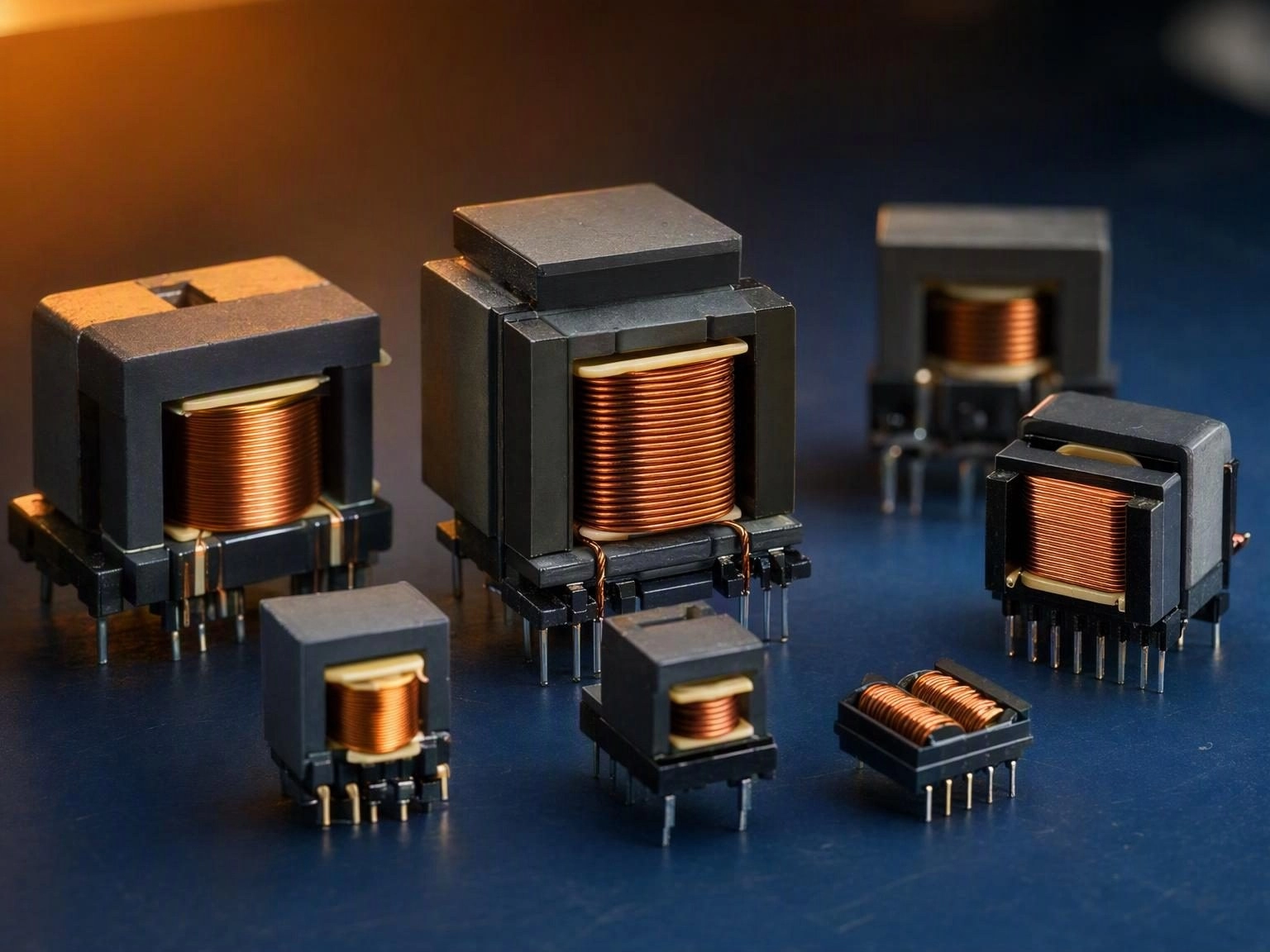
Transformer families are not interchangeable. EE and EI cores offer a familiar cost to performance balance for general purpose supplies. PQ cores pack a large winding window into a small footprint and suit medium to high power converters where board area matters. EFD and EP cores are low profile, which makes them the natural choice for slim adapter and LED driver enclosures. ETD and EER cores provide generous window area for high current secondaries.
- EE and EI cores for cost sensitive general purpose supplies
- PQ cores for compact medium and high power converters
- EFD and EP cores for low profile adapter and LED driver designs
- ETD and EER cores for high current and high power secondaries
- EDR and RM cores for shielded, space constrained applications
Winding Loss and Leakage Inductance
Core selection is only half the design. Copper loss rises sharply with frequency because of skin and proximity effects, and it is usually the winding rather than the core that limits how much current a small transformer can carry. Leakage inductance, driven by how tightly the primary and secondary are coupled, sets the voltage spike seen by the switching device and influences EMI. A transformer that meets its turns ratio can still fail in the field if these two parameters are treated as afterthoughts.
Thermal Margin and Insulation Requirements
Temperature rise is the final gate. A design that measures well on the bench at 25 degrees Celsius may reach a hotspot that degrades insulation or drives the core above its Curie temperature inside a sealed enclosure. Margin should be evaluated at the maximum ambient the end product will see, not at the lab bench.
Insulation and creepage requirements follow the safety standard the end product targets. Reinforced insulation for offline supplies, basic insulation for low voltage secondaries, and the associated creepage and clearance distances all constrain the bobbin and the winding sequence, which is why they need to be known before the first prototype rather than discovered during certification.
The Sequence We Recommend
Fix switching frequency and power, choose a core family that satisfies height and thermal constraints, calculate turns and wire gauge accounting for AC resistance, verify leakage inductance against the switching device rating, then confirm insulation and creepage for the target standard. Only then does a prototype make sense.
If you share your electrical parameters and mechanical envelope, our engineering team can review the specification, propose a core and winding strategy and deliver evaluation samples, typically within three to seven working days for standard configurations.