
Insulation Is a Safety Function
Every other parameter of a transformer is a performance question. Insulation is a safety question. If the insulation between a mains referenced primary and a user accessible secondary breaks down, the failure mode is electric shock, not degraded efficiency. That is why insulation systems are regulated by safety standards rather than left to the designer discretion, and why the construction of the bobbin, the tape barriers and the winding sequence matter as much as the electrical specification.
Creepage, Clearance and Solid Insulation
Three mechanisms provide insulation in a transformer and all three must be satisfied simultaneously. Clearance is the shortest distance through air between two conductive parts, and it protects against breakdown across a gap. Creepage is the distance along the surface of an insulating material, and it protects against tracking along a contaminated or humid surface. Solid insulation is the material between the windings themselves, including the wire enamel, tape barriers and the bobbin wall.
A design can pass a high potential test in dry air and still fail in the field if its creepage distance is inadequate for the pollution degree and humidity the end product will experience.
Insulation Classes and Temperature
Insulation systems are rated by the maximum temperature they can withstand continuously without premature degradation. Class B, F and H correspond to progressively higher limits, and the choice depends on the hotspot temperature the design actually reaches rather than the ambient temperature of the enclosure. A transformer running at a hotspot of 105 degrees Celsius needs a higher class than one that runs at 70 degrees, and selecting on ambient is a common and expensive mistake.
- Class B for lower temperature rise designs with generous thermal margin
- Class F for the majority of offline power supplies
- Class H for high density or high ambient applications
- Wire enamel, tape and varnish must all be rated for the same class as the system
Reinforced Insulation for Offline Supplies
Where a user can touch the secondary, the insulation between primary and secondary must usually be reinforced, meaning it provides two independent layers of protection. In practice this means a combination of wire enamel, a margin tape or triple insulated wire, and bobbin wall thickness that together satisfy the creepage and clearance requirements of the applicable standard. The construction cannot be improvised after the fact. It has to be designed into the bobbin and the winding sequence from the beginning.
What High Potential Testing Proves
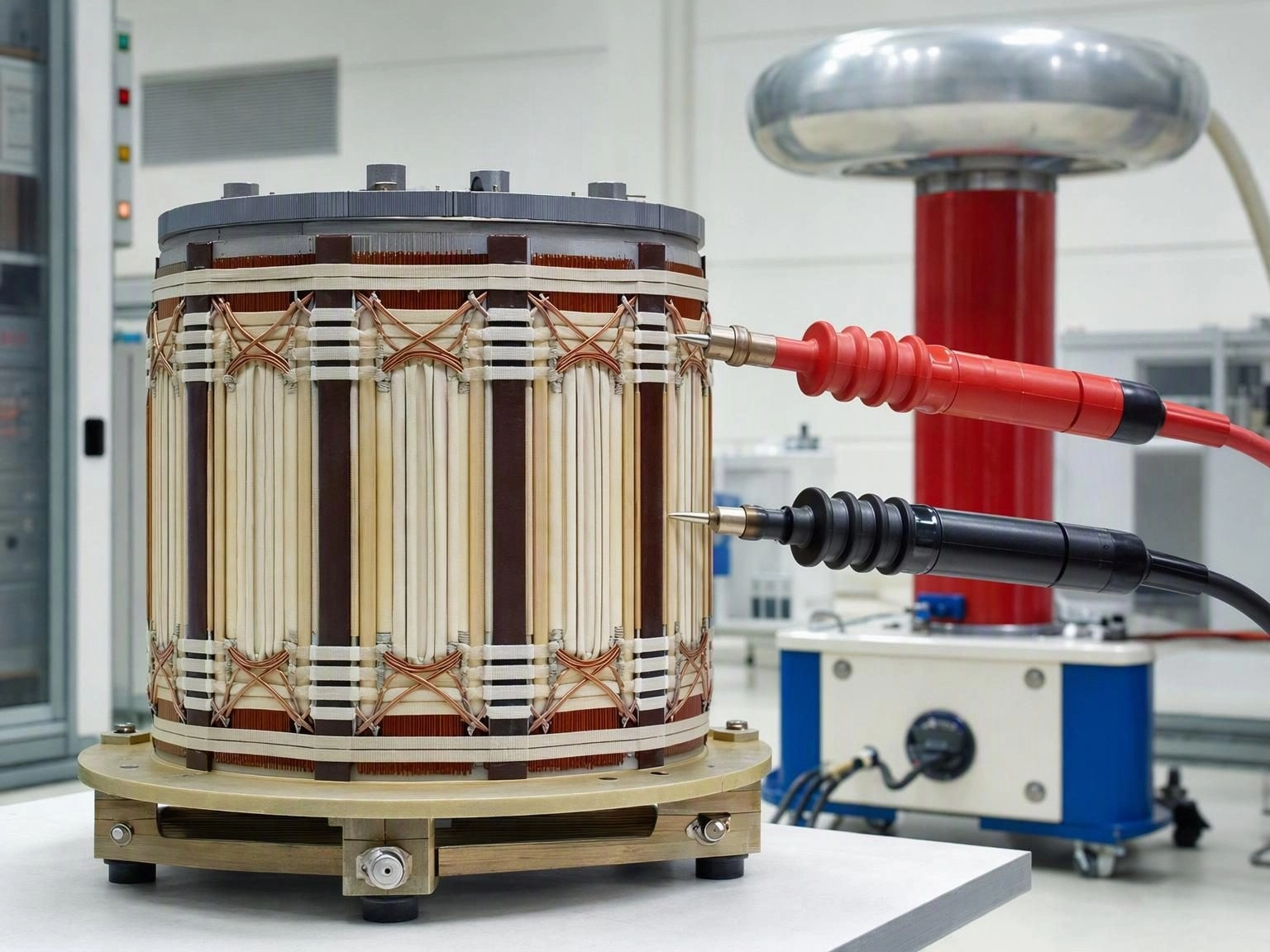
High potential testing applies an elevated voltage, typically several kilovolts for a short duration, between primary and secondary and between windings and core. It is a go no go test on the insulation system and it is applied to every production unit, not only to samples. It proves that the insulation did not break down at the test voltage and that no gross assembly defect has bridged the barrier.
What it does not prove is long term margin. A component can pass a production hipot test and still degrade if its creepage is marginal, its varnish coverage is incomplete or its hotspot exceeds the insulation class. That is why high potential testing is a final gate rather than a substitute for design.
Designing Insulation In From the Start
Confirm the safety standard and the insulation class before selecting a bobbin, because the bobbin geometry determines the creepage distance you can achieve. Choose wire and tape rated for the same temperature class as the hotspot, apply vacuum impregnation to fix the winding and improve dielectric strength, and verify the construction at the temperature extremes the product will see rather than at room temperature alone.
Our transformers are wound with insulation systems matched to the safety standard of the end product, and high potential testing is applied to every unit at final inspection with results retained in the production record.